- (03) 5909 8218
- enquiry@fusionweld.com.au
The purpose shell and tube heat exchangers
Oct 16, 2014
The purpose of the shell and tube heat exchanger has been clearly defined since the dawn of the industrial age. Two fluids flow through a shell. These two variables occupy partitioned pathways, never coming in contact. Fluid one flows through a complex series of highly conductive tubing within the shell while the second liquid occupies the volumetric space between the inner walls of the shell and the surface area of the tubing. It's this contact area that determines energy transferal, and it's the circulation properties of the second fluid matched with the conductive properties of the tubing that controls the efficient transmission of energy
The term fluid is used loosely in heat exchanger applications. Gases and liquids are common input variables in this scenario, and the heat transmission process varies from simple heat transference, known as 1-phase exchange, to advanced condensation and vaporization transactions that employ multiple stages, a 2-phase exchange model. A steam locomotive is a prime example of a heat exchanger transferring raw energy into pressurized steam. The core of the steam locomotive is a boiler, and it's this primal heat exchanger that's responsible for driving archaic but highly functional engines, powering the steam technology that moved a million pistons during the industrial revolution. Still, it's evolution not revolution that demonstrates the multitude of configurations in use today, the heat exchanger models that condense vaporized water and power steam-driven turbines in the bowels of power generation plants. It's also pressure differentials and particular applications that decide the role of each assembly, from industrial boilers to the condenser and evaporator coils used in environmental engineering.
The petrochemical industry adopts the same processing criteria as above, using heat exchangers filled with cooling water to condense gaseous products and manage the flow of 2-phase chemical derivatives throughout the tube bundle and the interior of a vessel. The vessel is designed with a horizontal architecture that promotes a cylindrical outline. Again, these design specifications are engineered to maximize surface area contact between the two fluids. Computer control systems informed by digital feedback sensors monitor the state of both fluids, managing temperature transference characteristics as defined by the TEMA standard (Tubular Exchange Manufacturers Association). These standards handle technical issues and dedicate engineering resources toward improving the current level of heat exchanger efficiency.
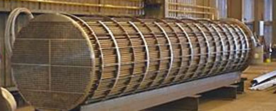
A complex mix of fluid dynamics and metallurgical standards go into improving vessel efficiency and tube fabrication. The tubes are held together by a sturdy mix of tie rods, baffles, and heat-resistant tube sheeting within the cylindrical structure. The blueprints of the vessel call upon intake and output components that can act upon the feedback being assessed by the electronic instrumentation in a nearby booth. Petrochemical industry or gas-turbine power generation, this control sequence is familiar across many industries. These critical mechanical assemblies include but aren't limited to pressure-tested flanges, front and rear headers, control valves, and a variety of shell specs rated for different pressures. Consult TEMA guidelines for further data on everything from flow ratio tolerances to plenum construction.
Contact Details
Fusion - Weld Engineering Pty Ltd
ABN 98 068 987619
1865 Frankston Flinders Road,
Hastings, VIC 3915
Ph: (03) 5909 8218
Optimized by NetwizardSEO.com.au
Recent Posts
- Pressure Vessel Fabrication: Engineering Efficiency for 2026 Petrochemical Projects
- Heat Exchanger Maintenance in Melbourne: Minimising Risk in Power Generation Facilities
- Compressed Hydrogen Storage Vessels: Material Selection, Design & Australian Standards
- Welding QA/QC in Oil & Gas Pressure Vessel Fabrication – Ensuring Code Compliance
- AS1210 vs ASME VIII Pressure Vessel Code: Key Differences for Australian Projects
- Mitigating Hydrogen-Induced Cracking in Pressure Vessels: Engineering and Material Strategies
- Storage Tank Solutions Australia: Field-Erected, Prefabricated & Self-Bunded Explained
- Reducing Environmental Risks: Self-Bunded Tanks in Australian Oil & Gas Operations
- Precision in Production: How Pressure Vessels Are Manufactured for Industrial Safety
- Shell & Tube Heat Exchangers: Improve Thermal Control & Energy Recovery in Petrochemical & Pharmaceutical Plants
- In-Service Inspection for Compressed Air Receivers for Power Plant Shutdown Prevention
- Power Plant Pipe Spooling Fabrication – Get Rapid, Code-Compliant Spools Ready for Installation
Posts 2026
- Pressure Vessel Fabrication: Engineering Efficiency for 2026 Petrochemical Projects
- Heat Exchanger Maintenance in Melbourne: Minimising Risk in Power Generation Facilities
- View all articles…
Posts 2025
- Compressed Hydrogen Storage Vessels: Material Selection, Design & Australian Standards
- Welding QA/QC in Oil & Gas Pressure Vessel Fabrication – Ensuring Code Compliance
- View all articles…
Posts 2024
- Large Process Vessels: Optimising the Design for Maximum Efficiency [2025]
- Pressure Equipment Management System Installation: Detect Equipment Faults Early
- View all articles…
Posts 2023
- Pressure Piping System Inspection: A Gift of Safety for the Holidays
- Deaerator Inspections by Fusion-Weld Engineering and How They Reduce System Downtime
- View all articles…
Posts 2022
- How Fusion Weld Keeps Up With AS-NZS ISO 9001:2008 Standard
- Boiler Equipment Safety Inspection During the Summer Season
- View all articles…
Posts 2021
- Avoid These Factors and Practices that Contribute to Sealing Damage in Pressure Vessels
- Do's And Don'ts Of Industrial Boiler Inspection And Maintenance From Fusion-Weld
- View all articles…
Posts 2020
- What are the Risks and Hazards Involved in Pressure Vessel Equipment?
- How to Know if Your Pressure Equipment Needs Repair or Replacement?
- View all articles…
Posts 2019
- Factors that Contribute to Pressure Vessel Failure
- Pressure Vessel Regulations in Australia: What are the Mandatory Requirements?
- View all articles…
Posts 2018
- Pros and Cons of Spherical vs. Cylindrical Pressure Vessels
- What are the Different Hazard Levels in Pressure Vessels?
- View all articles…
Posts 2017
- Transportable Pressure Vessels: The Importance of Inspection and Safety Checks
- Fracture Mechanics and Stress Analysis of Cracks in Pressure Vessels
- View all articles…
Posts 2016
Posts 2015
- What Are Deaerators & Feedwater Vessels?
- Precautions and Safety for Compressed Air Receiver Vessels
- View all articles…
Posts 2014
- Demonstrating In-process Inspection Procedures
- Static Grounding Practices and Standards
- View all articles…